

-320x320.jpg "MIG/MAG Welding Machines")
-320x320.jpg "TIG AC/DC Welding Machines")




-320x320.jpg "Electrodes for High-Alloy Steel")
-320x320.jpg "Surfacing Electrodes")
-320x320.jpg "Electrodes for Cast Iron")








-320x320.jpg "Welding Masks")




-320x320.jpg "Welding Machine Carts")






Wire Feed Mechanisms in Semi-Automatic Welding Machines
Published:
08/05/2026
Wire feed mechanisms in semi-automatic welding machines are responsible for smooth feeding of the filler from the spool to the torch. Their operation affects arc stability, weld quality, and the welder’s comfort. If the wire feed mechanism for a semi-automatic welding machine is selected correctly, the material moves without jerks, and the process remains predictable.
What a Wire Feed Mechanism Is and How It Works
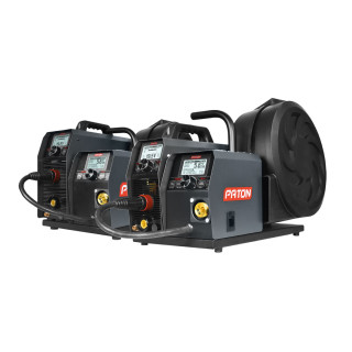
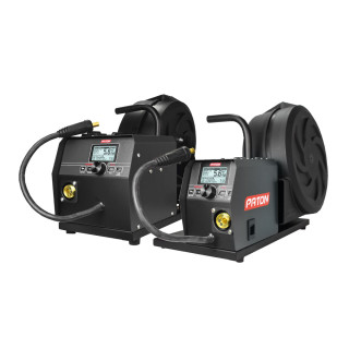
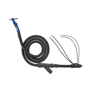
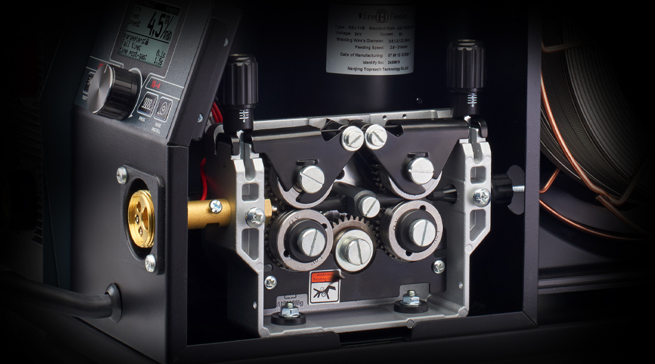
A wire feed mechanism for a semi-automatic welding machine is a unit that moves the filler material through the guide channel, hose package, and torch to the welding zone. It includes rollers, an electric motor, a gearbox, a drive, a pressure system, and a control unit. These elements set the feed speed and maintain stable pulling.
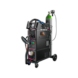
During operation, the spool rotates, the strand passes through the drive roller and pressure roller, and then moves into the hose package. The pressure system must hold it without slipping, but not deform it. For stable MIG/MAG welding, wire feed units are used, helping to control the process more accurately.
Main Types of Wire Feed Mechanisms
A wire feed unit for a semi-automatic welding machine differs in design, number of rollers, motor power, and method of moving the filler. The higher the load, the more important the quality of the gearbox, drive, and pressure adjustment.
When choosing, it is worth considering the main elements:
- rollers must match the diameter and type of consumable;
- the gearbox affects the smooth operation of the unit;
- the electric motor must maintain a stable feed speed;
- the drive is responsible for uniform pulling;
- the guide channel must be clean and properly sized;
- the control unit must adjust the parameters accurately.
If one of the elements works unstably, feeding occurs with delays, the arc becomes uneven, and the weld requires rework. Therefore, the wire pulling mechanism for a semi-automatic welding machine is selected according to the load.
Push Systems
Push mechanisms are the most common. In this system, rollers push the material from the spool through the hose package to the torch. The design is simple, easy to maintain, and suitable for most tasks with steel filler.
Feed quality depends on the hose package length, channel condition, pressure adjustment, and consumable type. With soft material or a long hose, bends and unstable pulling may occur.
Pull and Push-Pull Systems
Pull systems are installed closer to the torch and help pull the filler out of the channel. Push-Pull combines a push and pull drive, so the feed remains smooth even when working with soft materials, such as aluminum.
Such solutions are needed where a standard feed unit does not provide stability. Push-Pull is useful with a long hose package, high feed speed, and work with thin consumables.
How to Choose a Wire Feed Mechanism for a Semi-Automatic Welding Machine
Before choosing, it is important to consider the machine type, filler diameter, material, hose length, and work intensity. For household tasks, a two-roller mechanism may be sufficient, while for production, it is better to choose a four-roller unit with a reliable drive.
It is also important to use high-quality welding wires, because even a good mechanism cannot compensate for poor winding, contamination, or unstable filler diameter. The consumable must unwind freely from the spool and not overload the electric motor.
The wire pulling mechanism for a semi-automatic welding machine affects arc stability, weld quality, and working comfort. To keep the feed smooth, it is necessary to consider the unit design, rollers, pressure system, drive, hose package length, and the type of filler used.